Showing posts with label machining tools. Show all posts

Tuesday, November 3, 2009

Parts of a Vernier Caliper

A Caliper is simply a measuring device from a compass to intense instruments such as the vernier caliper acting as an advanced ruler. The vernier caliper uses vernier scale to measure more precisely. This instrument provides different methods of measuring including ways to measure external or internal dimensions as well as finding depth measurements. In fact the depth measurement method of using a movable and slidable probe is so slender that it is able to retrieve data in deep canals.

You have to be familiar with the instrument in order for your to achieve an accurate measurement. Any discrepancy from of measurement even for just a few millimeters will spell success of trouble for you. Machinist are experts on this device. But evenso, they still need to exercise caution.

The lower and upper section of this scale generally uses both inch and metric measurements. Industries use vernier calipers because of its hundredth of a millimeter precision equal to one thousandth of an inch. Below describes the vernier caliper's parts and functions.


Vernier Caliper
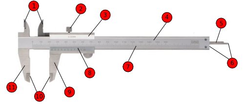
The rail (4) allows sliding to occur on the main scale (7) moving the vernier scale (3) while the fixed jaw (11) remains in place so the precise measurement is found. Also, draw back and forth (9) the instrument's jaws (parts 1 and 10) to adjust the caliper. The indicated measurement is found at the left of the vernier scale (3 and 8) either in inches or centimeters. The sliding jaw (9) and the depth probe (5) are connected to and move along with the vernier scale. Deep measurements are taken by the use of the front end of the rail (6).
  1. Inside jaws: Internal length measurements are found by using this part.
  2. Retainer or locking screw: This part blocks the instrument's movable parts in order to transfer between measurement methods easily.
  3. Vernier scale (inch)
  4. Rail (inch)
  5. Depth probe: The part used in order to find depth measurements
  6. Front end of the rail
  7. Main scale (mm)
  8. Vernier scale (mm)
  9. Sliding Jaw
  10. Outside jaws: This part makes measuring external lengths possible.
  11. Fixed Jaw


source

Saturday, October 31, 2009

The Vernier Caliper

The Caliper. The name itself is generic. But to define it, it is a device used to measure the distance between to symmetrically opposing sides. A caliper can be as simple as a compass with inward or outward-facing points. The tips of the caliper are adjusted to fit across the points to be measured, the caliper is then removed and the distance read by measuring between the tips with a measuring tool, such as a ruler.

They are used in many fields such as metalworking, mechanical engineering, gunsmithing, handloading, woodworking, woodturning and in medicine.

There are many types of Calipers but obviously in relation to this blog, we'll mention a particular type of caliper namely: The Vernier Caliper.

Vernier Calipers are usually found in machine shops or any other area which requires to measure its fabricated dimensions. Without this device, machine shops will be having a hard time for accurate measurement.

Vernier calipers can measure internal dimensions (using the uppermost jaws in the picture at right), external dimensions using the pictured lower jaws, and depending on the manufacturer, depth measurements by the use of a probe that is attached to the movable head and slides along the centre of the body. This probe is slender and can get into deep grooves that may prove difficult for other measuring tools.

The vernier scales may include both metric and inch measurements on the upper and lower part of the scale.

Vernier calipers commonly used in industry provide a precision to a hundredth of a millimetre (10 micrometres), or one thousandth of an inch.

A more precise instrument used for the same purpose is the micrometer.


source

Sunday, October 25, 2009

XYZ takes orders: expands services

A recent series of Open Days hosted at XYZ Machine Tools Ltd's regional showrooms resulted in orders valued at nearly £700,000, while details of expanded services were announced.

XYZ takes orders expands servicesThe show, held in Blackburn, Nuneaton and Waltham Abbey, saw orders for CNC/manual mills and lathes and full-CNC machine tools, and this, said managing director Nigel Atherton, provided the backdrop to what he sees as a more positive attitude to capital investment from manufacturing industry.

"There are clear signs of an improvement in business confidence," he said, "although it is still too early to be sure that this is more than a blip and that the worst of the recession is behind us. However, we had visitors representing more than 60 companies, and the interest shown, the orders placed and the enquiries in progress are very encouraging."

Price, of course, is a key factor in any capital equipment purchase but, said the managing director: "We believe it is vitally important to help our customers lower the overall cost of machine tool ownership. One way of achieving this is by providing high quality service and support, together with better and more efficient training. This is why we are expanding XYZ's training and applications team, with these latest open days coinciding with an extension of the team's customer service remit."

Customers already receive basic training free-of-charge when purchasing an XYZ machining centre, turning centre or large CNC lathe equipped with Siemens CNC, or any CNC/manual turret/bed mill or lathe equipped with the exclusive ProtoTRAK control. The Burlescombe, Devon-based company also organises refresher and advanced training days designed to help users of its machine tools to obtain the maximum benefit from their investments. Now it is extending the help available to customers buying its Siemens-equipped full-CNC machine tools with the offer of up to eight days free-of-charge applications assistance worth up to £4,800.

"This is additional to the three days' free-of-charge basic training already provided with our full-CNC range of machines," Mr Atherton underlined. "Our objective is to speed up the learning process and to help customers avoid the frustrations that can occur following installation and commissioning of a CNC machine. The first few days are when even the most experienced operator taking on a new control can produce expensive scrap, bad habits can take hold and valuable time can be wasted. However, with expert applications assistance on hand in your machine shop, this need never happen."


source

Saturday, October 24, 2009

Mills CNC claims big market share for big machines

Mills CNC claims over 50 per cent of the UK's large lathe market (chuck size 12" and over), 50 per cent of the large VTL (Vertical Turning Lathe) market and significant market share in the large horizontal machining centre and horizontal borer markets.

Mills CNC claims big market share for big machinesThe company is the exclusive UK and Ireland distributor for Doosan machine tools, and highlights that the portfolio has recently been broadened with the launch of a new range of 5-face, double-column machining centres, DCM, within which there are eight different sized.

The new DCM machines, with up to 10, 250 by 4,200 by 700, by 1,100 mm in X, Y, Z and W, can parts up to 68,000 kg in weight.

Depending on the type of application, DCM machines can be specified with various ram spindle configurations (heavy-duty cutting through to high-speed/high-torque options); different head attachments and table types.

"The Doosan big machine tool range is impressive – and the new DCM machines are no exception," underlines Nick Frampton, Mills CNC's managing director.

"In terms of breadth, depth, technical specification, and all-round performance and price – big Doosan machines are the number one choice for precision manufacturers in the oil and gas, power generation and other sectors where the machining of large components is at a premium."


source

Saturday, October 17, 2009

Lathe Tools offer maximum speed of 12,000 rpm.


SMW Autoblok is pleased to introduce spindle speed increasing Live Tools for Haas lathes. These new low-profile Live Tools feature a 1:3 speed increasing ratio and a maximum speed of 12,000RPM.

Designed to increase the performance of Haas lathes with 4,000RPM driven turrets, SMW Autoblok's new spindle speed increasing Live Tools can drastically reduce cycle times and duty cycles, particularly in finishing application in mild steels, aluminum, plastics, and reinforced resins. With an ultra-low profile of 88.5mm (3.48"), these new Live Tools are no taller than a standard Live Tool, preserving Z-axis clearance for work-holding and parts. Additionally, with their minimal width of 80mm (3.15"), they do not interfere with adjacent tools in the turret.

SMW Autoblok's new spindle speed increasing Live Tools utilize patented square drive Gleason matched ground helical gears for improved torque transmission and high quality twin interlocking labyrinth seals to prevent contamination from coolant and chips. The new compact ER clamping design makes for easy tool changes, higher clamping forces, extended drill lengths, and improved rigidity.

SMW Autoblok also offers standard Live Tools for Haas lathes in straight, right angle, and offset styles equipped with either an ER Collet or Face Mill output spindle. Coolant-thru the tool up to 1,000PSI is available on most styles, and special application Live Tools are available upon request. SMW Autoblok stocks Live Tools for other popular CNC Turning Centers including Mazak, Mori Seiki, Okuma, and Doosan and more.

For more information on Live Tools or other SMW Autoblok products, please contact SMW Autoblok Corporation at 847-215-0591 or visit www.live-tooling.com.

ABOUT SMW AUTOBLOK CORPORATION - Autoblok Corporation was established in 1981 as a subsidiary of Autoblok of Italy, the largest power chuck manufacturer in Europe. Since 1942, Autoblok has been at the forefront of engineering and manufacturing state-of-the-art workholding, clamping and tooling solutions. In 1993, Autoblok acquired SMW of Germany. The combination of these two premier manufacturing entities resulted in the most extensive product line of high quality workholding devices in the world. Now available exclusively through its subsidiaries, reps and distributors, SMW AUTOBLOK customers are ensured a consistent, single source of superior product performance, support and service.


source

K+K moves to expand machining business

Bletchley-based subcontractor K+K Specialised Engineering has moved to new premises to accommodate extra XYZ CNC machine tools and allow for future growth.

Prototype electronics box milled from solid aluminium block by K+K Specialised Engineering

The company currently machines precision components for the automotive development, motorsport, microwave communications and mechanical handling industries, as well as making jigs and fixtures for UK-based metrology companies.

Commenting on the move K+K director Keith Pain explains: “We would not have done this if it did not make sound economic sense. Our problem, if you can call it that, was that we had become the favoured supplier to several businesses that had also flourished by being responsive to their customers. We were regularly being asked to produce small batches of components instead of just one-offs in extremely short timescales.”

The fact that, typically, there is a very high percentage of metal removal from the raw material is key to the solution that has been adopted by K+K.

“In this situation additional machining centres are able to increase the output without any increase in the workforce,” says Keith Pain.

A significant part of K+K’s recent investment involves two new compact vertical machining centres supplied by XYZ Machine Tools Ltd. These are installed alongside an identical XYZ Mini Mill 560 that K+K has operated for several years. During urgent batch production all three are typically machining similar components, with the cycles phased so that the operator can tend each machine in turn as required. In fact, there is often spare time during which the operator can progress jobs on one of the other, slightly less automated, mills.

The choice of two more XYZ Mini Mill 560s was not only because of the good value that made the economics viable but also the experience gained with the existing machining centre. “Our machine tools have progressed according to the needs of the work and drafting technology,” says Keith Pain. “When we started nearly all drawings were manual and most jobs were one-offs, so manual machines with digital readouts were all that was really necessary, and indeed all we could afford.

"When economic CNC machining arrived we were aware of the benefits, particularly in the case of small batch work, although we investigated several options before investing in a basic XYZ ProtoTRAK-equipped CNC/manual lathe and then a ProtoTRAK CNC/manual mill."

With ever more information arriving as CAD models, and the increase in repeat components, the Mini Mill 560 was the logical next step.

Ideally suited to the type of work and batch sizes typically undertaken by K+K, the concept behind the XYZ Mini Mill 560 is a compact VMC configuration capable of machining the widest possible range of components within the smallest possible machine footprint. A 560 mm (X) by 400 mm (Y) by 500 mm (Z) working envelope is contained within a 2000 mm (width) by 2060 mm (depth) footprint.

www.xyzmachinetools.com


source

Tuesday, September 22, 2009

Choosing a Cutting Tool


The figure above shows a typical cutting tool and the terminology used to describe it. The actual geometry varies with the type of work to be done. The standard cutting tool shapes are shown below.

  • Facing tools are ground to provide clearance with a center.
  • Roughing tools have a small side relief angle to leave more material to support the cutting edge during deep cuts.
  • Finishing tools have a more rounded nose to provide a finer finish. Round nose tools are for lighter turning. They have no back or side rake to permit cutting in either didection.
  • Left hand cutting tools are designed to cut best when traveling from left to right.
  • Aluminum is cut best by specially shaped cutting tools (not shown) that are used with the cutting edge slightly above center to reduce chatter.

Standard Cutting Tools


source

Thursday, September 10, 2009

How to Choose a Lathe Machine


Lathe machines are machines built to serve a specific purpose and even though there's a lot of variety to choose from, you really must choose the one that suits your needs the best. The average hobbyist will likely be best off with a mini lathe, which has a limited scope of operations but can be very useful for small and personal projects. These are mainly used by beginners who are testing the waters for turning out shapes and designs.

Whilst these mini lathes are not at all suited for professional lathe projects, those who want to make a slower transition to bigger lathe machines do have options to upgrade their mini lathe machines. These upgrades add functionality like variable speeds, arms etc. This also makes sense for those who want more out of their machine without spending a lot of money for a new and bigger machine.

However, there is a limit to how much a basic lathe machine can be upgraded, so it is advisable that professionals who have discovered the power of a lathe machine upgrade to as big a lathe as they possibly can. This is meant for those craftsmen who can see a long future of them using the lathe machine. For those who are unsure of how long they will use one or those who are on a tight budget, there are mid segment lathe machines that usually have a size between 12x34 and 16x36. They cost in between $400-600 and offer enough features and sturdiness for the professional craftsman without burning a hole through his pocket.

There are a few things to consider before jumping in and buying the cheapest or the biggest machine out there for your budget. You need consider the spindle you are getting. The spindle is the core to the operations of lathe machines and they come in standard and non-standard sizes. The is usually a good idea to go for standard sizes like the 1"x8tpi spindles. The bed capacity is also important, as this will determine the size of material with which you can work. Variable speed is another aspect because most professionals prefer to work at different speeds while doing different things to the material. Like for sanding you would prefer a higher speed but for carving, you might want a medium to low speed depending on the detail you want to work in.

Be careful of cheap lathe machines because their parts are often non-standard and are hence very easy to replace. As with other power tools and hardware, buying from a reputed company is always advisable. If you are buying used machines, do not purchase without getting to check it out first. For used lathe machines, try to purchase locally from a shop you know. If you are buying over the Internet even, try to buy from somewhere nearby and pick it up yourself after checking it out properly. Again, keep in mind the purpose of your machine while making a purchase.


source

Monday, September 7, 2009

Parts of the Lathe Machine


The lathe is a machine tool used in metal cutting operations called "turning." The work piece is rotated as tooling is applied to it to remove material. Lathes can be manually operated or operated by computer numerical control (CNC). In either case, the basic parts are similar.


The Bed

1. The lathe bed is a mounting and aligning surface for the other machine components. Viewed from the operating position in front of the machine, the headstock is mounted on the left end of the bed and the tailstock on the right. The bed must be bolted to a base to provide a rigid and stable platform. The bed ways are a precision surface (or surfaces) on which the carriage slides left and right during machining operations. The ways are machined straight and flat and are either bolted to the top of the bed or are an integrally machined part of the bed.

Headstock

2. The headstock holds the spindle and drive mechanism for turning the work piece. The spindle is a precision shaft and bearing arrangement rotated directly by a motor or through a motor-driven belt. Gears or sliding pulleys mounted at the rear of the headstock allow spindle speed adjustment.

A work piece is held in the spindle for turning or drilling by a jawed chuck or a spring collet system. Large, unusual shaped, or otherwise difficult to hold pieces, can be attached to the spindle with a face plate, drive dogs and special clamps.

Tailstock

3. The tailstock supports long work that would otherwise sag or flex too much to allow for accurate machining. Without a tailstock, long pieces cannot be turned straight and will invariably have a taper. Some tailstocks can be intentionally misaligned to accurately cut a taper if needed. The tailstock has a centering device pressed into a shallow, specially drilled hole in the end of the work piece. The center can be either "live" or "dead." Live centers have a bearing, allowing the center to rotate along with the work piece. Dead centers do not rotate and must be lubricated to prevent overheating due to friction with the work piece. Instead of a center, a drill chuck can be mounted in the tailstock.

Carriage

4. The carriage provides mounting and motion control components for tooling. The carriage moves left and right, either through manual operation of a hand wheel, or it can be driven by a lead screw. At the base of a carriage is a saddle that mates and aligns with the bed ways. The cross-slide, compound rest and tool holder are mounted to the top of the carriage. Some carriages are equipped with a rotating turret to allow a variety of tools to be used in succession for multi-step operations.

Cross Slide

5. The cross-slide is mounted to the top of the carriage to provide movement perpendicular to the length of the bed for facing cuts. An additional motion assembly, the compound rest, with an adjustable angle, is often added to the top of the cross slide for angular cuts. The cutting tools that do the actual metal removal during turning are mounted in an adjustable tool holder clamped to the compound rest.

Lead Screw

6. The lead screw provides automatic feed and makes thread cutting possible. It is a precision-threaded shaft, driven by gears as the headstock turns. It passes through the front of the carriage apron and is supported at the tailstock end by a bearing bracket. Controls in the apron engage a lead nut to drive the carriage as the lead screw turns.


source

Different Types of Lathe Machines

Lathes literally keep the manufacturing world spinning. Almost all manufacturing companies have their own lathe machines. A lathe works by spinning a piece of material, such as wood or metal, at a high speed while a cutting tool is applied to the rotating material. The result is a symmetrical cylinder.


Below is a list of the different kinds of lathes being used today.


Wood Lathes

1. Popular with both hobbyist and professionals alike, the wood lathe makes everything from baseball bats to chair legs and bedposts. Most round wood pieces are spun on a wood lathe to achieve a smooth feel and look.


Metal Lathes

2. Found mostly on factory floors, and often hooked up to computers with robotic arms, metal lathes are used for precision operations like threading and boring.


Glass Lathes

3. Whether forming the next piece of high-end art or filling an order for a scientific lab, glass workers use a lathe to shape their medium. Glass lathes safely spin glass tubing over a flame until the material is pliable for shaping.


Pottery Wheel

4. The pottery wheel is the only lathe where the operator may safely use her hands to shape the material. Though most lathes are horizontal, the pottery wheel spins its material about a vertical axis.

Fun Fact

The pottery wheel has been around for thousands of years, dating back to ancient Egypt and Mesopotamia.


source

Monday, July 27, 2009

what is a lathe machine?


you can see this when you visited or just pass by a machine shop. this equipment is very visible but most people don't know what kind of equipment is it. Even big industrial companies have this kind of machine in their engineering or machine departments. to the common man, this machine may seem nothing, but for those who knew the value it, it is almost priceless. Welcome to the world of Lathe Machines. Read More.....

Wednesday, July 1, 2009

General Tools & Instruments

General Tools & Instruments, began as the brainchild of Abe and Lillian Rosenberg in New York City, 1922. Originally dubbed General Hardware Manufacturing Co., the company specialized in the wholesale of “hard goods,” offering a full-range of domestic and professional items from clothesline pulleys and screen-door hardware, to specialty hand tools.

However it wasn’t long before Abe, a former WWI soldier and a vibrant, creative thinker, began to conceptualize his own product ideas. With Lillian running the store, Abe would take the Fall River Line from Greenwich Village to New England in search of machine shops to manufacture his tools. By 1930 he had outsourced a small line of specialty items, including circle cutters, metal punches and pocket screwdrivers. By 1937, Abe and Lillian were selling their own products exclusively at General Hardware.

Abe continued to develop a line of useful products for both consumer and commercial purposes. His thirst for new ideas kept General at the forefront of the industry and, accordingly, the company became one of the first to build die-cast tools. Through Lillian’s keen business management, the company was awarded contracts supplying machinist tools to the United States Military and the British Purchasing Commission during WWII. In 1946, General became a charter member of the Sears 100 Club of Craftsman tool suppliers.

Upon Abe’s death in 1977, his daughter Dorothy became Chairman of the Board. Along with her husband, Seymour Weinstein, Dorothy expanded General’s product line to include precision measuring tools and other specialty hand tools. In 1990, the company’s name was officially changed to General Tools to better reflect its product line.

Today, General Tools is run by Dorothy’s son Gerald Weinstein. Under Gerry’s leadership, General has expanded its product line to include electronic testing and measurement equipment, fueled by the much-heralded acquisition of Mannix Instruments in November of 2006. The company, now General Tools and Instruments, continues to forge a path into the digital marketplace all the while holding true to the entrepreneurial spirit upon which it began.


Comment:

A must for every machine shop

www.generaltools.com